The TRS-20 - make it run
.jpg)

My Z8018010VSC processor is here!
Also arrived is the LCD screen, the STM32F401CC dev board, and most of the other junk I ordered. This post explores what else I need to prepare to be able to make something operational.
The minimum circuit for the Z180 will need a power source and a clock. With only these things supplied, the processor will be shouting addresses into the void and receiving opcodes to execute from the ether, so tying some of the address lines to LEDs, the data lines to 00H (aka NOP), and other input lines high will let me confirm the processor is running.
The PLCC sockets are through-hole parts, allowing me to simply use perf board to get some kind of initial circuit up and running. Power can be supplied by header pins fed from a 5V breadboard supply, and a cheap oscillator in a DIP socket gets me a clock source quickly.
With clock and power sorted out, it’s time to look at the signals. The PLCC chip has 68 pins, of which 5 are supply pins (four Vss, one Vcc) and two are clock input pins (EXTAL and XTAL, only EXTAL needed with an oscillator). This leaves 61 signals and two power lines to sort out. TEST must be left floating, and RFSH is pointless without DRAM, which leaves me with 61 lines to assign. I can use a 10-pin header for the serial signals and a 50-pin IDC header for everything else, with one signal to discard. I’ve chosen to leave out the E secondary bus signal, which is active only when bus requests are active.
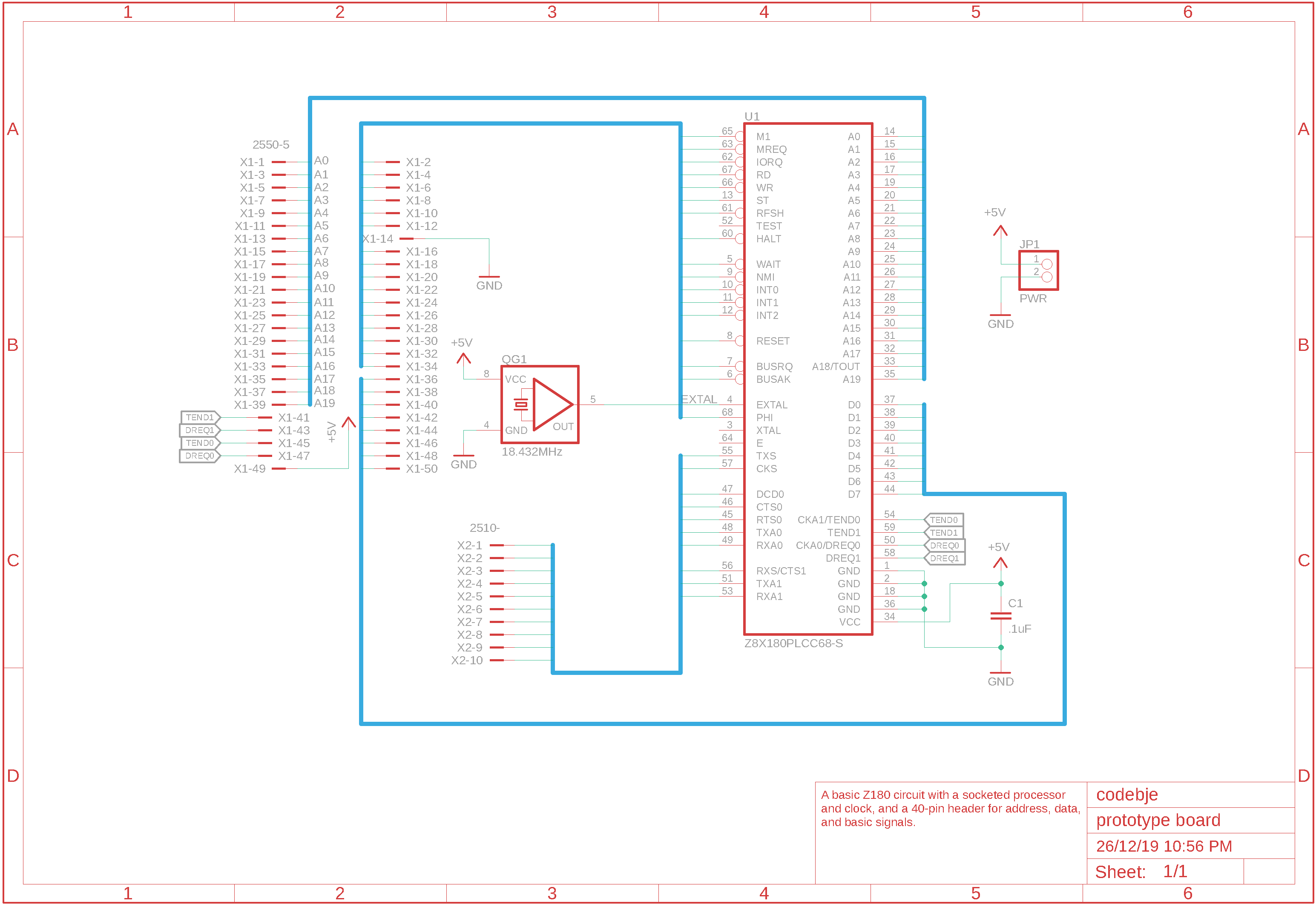
Soldering 60+ wires to perfboard is a fiddly task, as I need to take care to solder wires on in an order that doesn’t leave me melting one wire while trying to solder another. I also don’t want to wind up with something looking like the banner image of this post. This means carefully inspecting the processor’s pin diagram and arranging the order of signals on the IDC connector to avoid crossing the wires. Selecting a non-interfering wire order now will have later benefits should I get a PCB made up, as I can stick to routing signals on the top layer and have a broad ground plane.
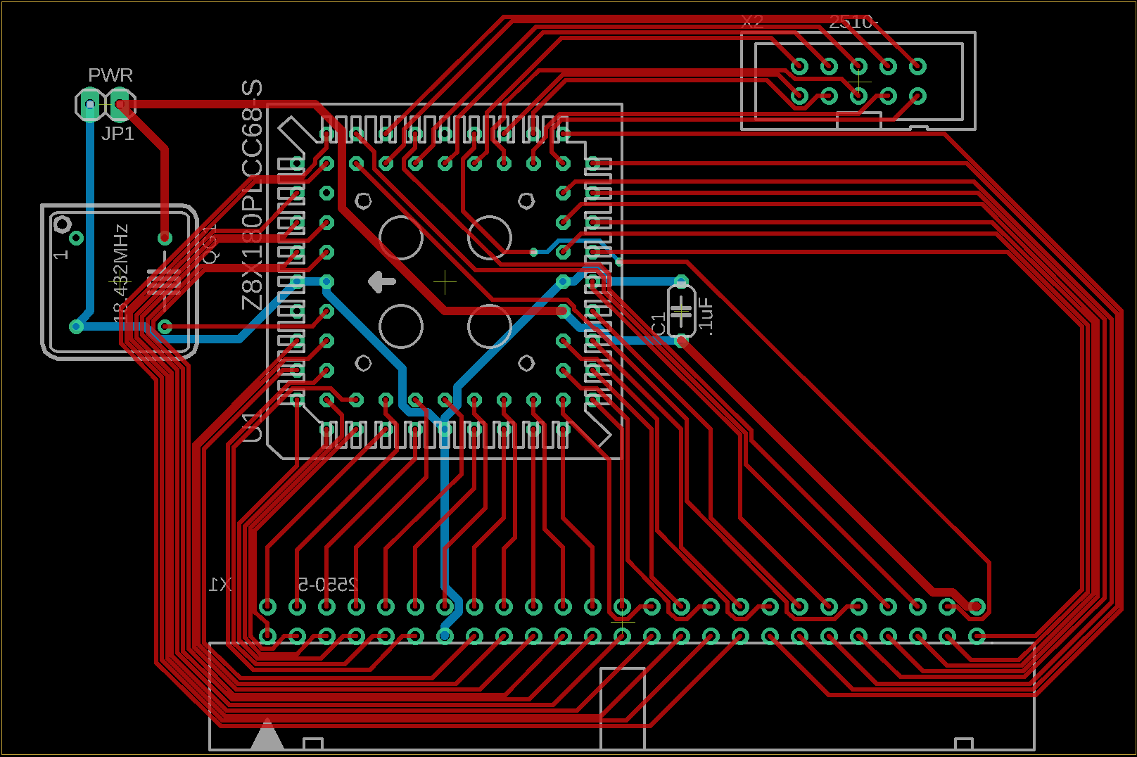
I need to run supply and ground on the bottom layer in a few places, and there’s a short stint on the bottom layer for DREQ0, but otherwise everything is on the top layer. This particular circuit is more of a wiring plan for a breadboard than anything else, as I think it would not be a good idea to run traces underneath an oscillator, for example.
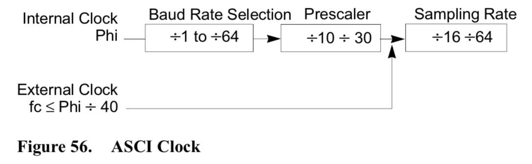
The Z80180 cannot run slower than 0.5MHz, by the datasheet. The processor’s clock runs at one-half of the external oscillator’s rate, so a 1MHz oscillator is the slowest that I can use. However, if I want to communicate over the USART, I need a clock rate that can work with the USART’s baud rate generator divider pipeline. This pipeline first divides my external clock by two to get the system clock. This can then be divided by a power of two from 1 to 64, then by 10 or 30, and then by 16 or 64. If I want to run my ASCI at 9600 baud, I need a clock that’s at least 16 x 10 x 2 x 9600 = 3.072MHz. Regrettably, DigiKey don’t want to sell me a through-hole oscillator at that speed, nor at 9.216MHz, or in fact any of the speeds that divide into a common baud rate, except for 6.144MHz and 18.432MHz. The latter clocks my processor at 9.216MHz and allows me to operate at baud rates from 57600 down to 300.
Alternatively, an external clock that’s less than or equal to the system clock divided by 40 can be used, divided by 16 or 64. A 1MHz oscillator is a 500KHz system clock, requiring an external clock slower than 12.5KHz. Since I have to divide it by 16, I’d need a 4.8KHz oscillator, which I’m pretty sure don’t exist. I’m calling this option a dead end - I don’t want to have a large BOM just to be generating a USART-compatible clock when I can use a system clock that’s suitable.
So: two oscillators. One to run the processor at its lowest speed of 500KHz with no serial access, and one to run it near its top speed at 9.216MHz. At low speeds, don’t expect serial comms to work: it’s flashing lights and I/O decoders all the way. At the higher speed, I should be able to run a USART link at up to 57600 baud. I can also consider a third oscillator at 3.57MHz, which runs the processor at 1.785MHz, as close as I’m likely to get to the 1.774MHz of the original TRS-80 Model I. To have both a TRS-80 Model I and USART at the same time would require an external clock source for the USART. An MCP2221 USB to USART bridge can output various clocks, with a stack of glue to divide down to a useful speed, or the CPLD may be able to generate a useful clock signal.
The 50-way IDC connector needs 2x25 holes, and is 2.54mm x 25 + 7.62 + 0.3 = 71.42mm wide. Jaycar’s got a 29x50 hole perf board that comfortably fits everything with plenty of space for wires. And a handful of other stuff: some sockets for logic chips, a larger 24x67 perfboard, and a 50-pin IDC header. Jaycar also gave me a $10 loyalty reward, bringing the price of this little splurge down to a more manageable level.
| Item | Price | Purpose |
|---|---|---|
| PI6501 | $1.35 | 14-pin IC sockets, for debug board |
| PI6502 | $0.90 | 16-pin IC sockets, for debug board |
| HP9554 | $8.95 | 24x67 hole perf board, debug board |
| HP9552 | $6.95 | 29x50 hole perf board, as initial CPU board |
| PP1116 | $0.95 | 50-pin IDC header |
This board is beyond bare-bones: the CPU won’t run correctly with just this board. There’s a handful of inputs that need to be tied high or low, including /RESET. With everything except E exposed, however, it’s fairly straightforward to plug into a breadboard to get something going, and to subsequently build a companion board with the STM32F4 to get some traction on doing more interesting things with the CPU.
| Budget | CPU | Power | Keyboard | Video | Memory | Debug |
|---|---|---|---|---|---|---|
| $63.13 of $400 | █─── | ──── | ──── | ──── | ──── | █─── |