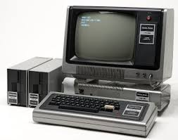
The TRS-20 - boot up

My 128 bytes each of ROM and RAM are working: the Z180 is executing my code.
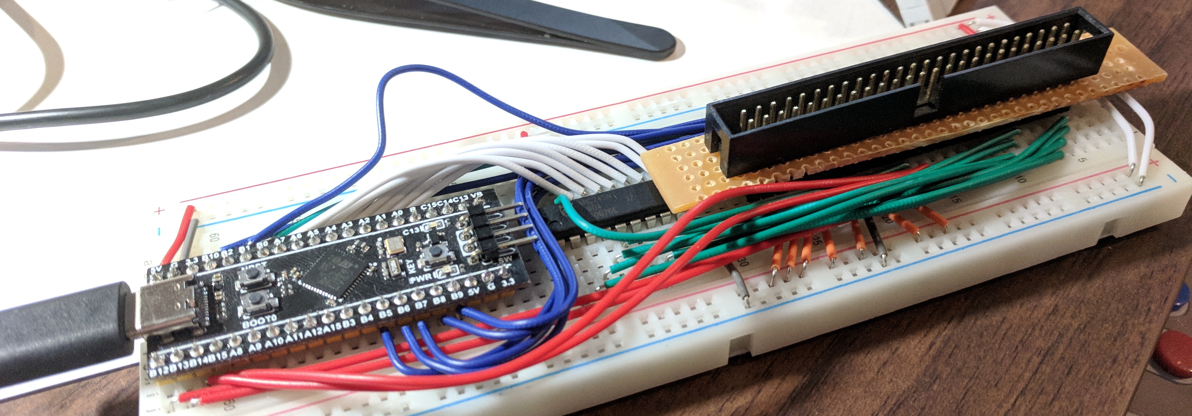
With my test rig re-wired using 22AWG wire (from a kit, I don’t have a nice stock of the stuff to trim to length myself yet) and looking neat, despite still only having eight address lines, I fired the thing up. Not pictured is a small extension that ties RESET high with a 10k resistor and adds a tactile switch to pull it low, as the Z180 doesn’t really behave properly without being reset.
The code that should be executed disables DRAM refresh, so my logic analyser images don’t have so much noise in them. After that, it just loops forever not doing anything.
reset:	.org	$0000
	ld	a, 0
	out0	(RCR), a	; disable the DRAM refresh
	jp	_start

; … other RST vectors omitted …

_start:
	nop
	jp	_start
After a reset, the data lines look like this. I’ve added handy little labels for the signals.
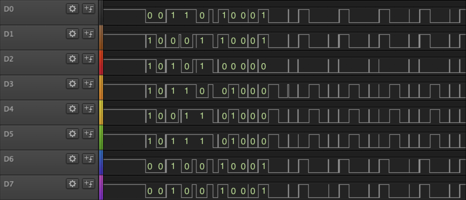
Decoding and cross-referencing these binary values with the listing file for the ROM image shows it executing exactly what it should, and it’s apparent that immediately after the out0 the DRAM refresh ceases, and the CPU repeatedly requests the nop and jp instructions
| bits | hex | assembly |
|---|---|---|
00111110 |
3E |
ld a, 0 |
00000000 |
00 |
|
11101101 |
ED |
out0 (RCR), a |
00111001 |
39 |
|
00110110 |
36 |
|
11000011 |
C3 |
jp $0038 |
00111000 |
38 |
|
00000000 |
00 |
|
00000000 |
00 |
nop |
I don’t think I’ve convinced friends or family that this is, in fact, quite an exciting milestone. Nevertheless, it is: I have written code that runs on my CPU. The rest of the computer is just details…
The STM32’s usefulness for this stage of the project is, I think, now at an end. It may return as a USB keyboard controller down the line, but this project is ready for PCB design.
Meanwhile, the PC104 headers I ordered arrived, after 84 days. My guess is they fell behind something in Customs and were only recently found. They were very well packed, and are undamaged, so I contacted the seller and placed another order that the seller didn’t ship. Since my refund didn’t include the tax I paid, and my new order did, I’ve now paid twice the tax on the headers, taking their total cost up to $12.70 for five 40-pin headers and two 64-pin headers. My stand-offs also arrived, so there’s now nothing in transit.
I also ordered and received an Altera MAX II CPLD minimal development board, for $11.56. This board saves me a lot of fiddly soldering making my own on perfboard, and will let me trial the use of a relatively cheap CPLD IC for address decoding or video output. I booted up Intel’s Quartus II to a sufficient level to verify the board works - to cut a long story short on it, it’s just a lot easier on a Mac to run Quartus in a desktop Linux VM than it is to try to make it work in Docker.
I’m going to mark the Debug section of the project as complete. It’s possible I’ll need further debugging aids later in the project, but each quarter I’ll want to review my targets and check they still make sense given what I’ve learned so far.
| Budget | CPU | Power | Keyboard | Video | Memory | Debug |
|---|---|---|---|---|---|---|
| $233.61 of $400 | ██── | ──── | ──── | ──── | ──── | done |