The TRS-20 - ROM programming

The last post left off after soldering on the FPGA and its companion parts: the SPI Flash ROM, the 100MHz oscillator, all the power parts, and the programmable LEDs. The only way to know if it’s been designed properly and attached to the board without error is to have it do something observable, like control the LEDs. And the only way to do that is to program the SPI ROM.
The easy way is to order a ROM programmer that can handle SPI Flash ROMs (and, preferably, also handle the parallel ROM). But what would I learn from that?
Instead, let’s use my STM32 “black pill” board as a programmer, using the USB serial interface to control it. The STM32 is a 3.3v board with an on-die SPI controller - with only one hitch. My black pill no longer powers up. I’ve no idea why, it seems to be failing to get power through the USB C socket, but there’s nothing wrong by a visual inspection.
Oh well.
The idea works well enough for me that I don’t want to just leave it there. Instead, I’m replacing my black pill board with a Nucleo-64, specifically the NUCLEO-F411RE. This is a slightly improved IC compared to the black pill’s STM32F401CC, and the Nucleo board is likely to be a higher quality product than a $6 part from an anonymous manufacturer. The Nucleo-64 board format has enough pins for me to directly program the parallel ROM without using shift registers.
SPI Flash wiring
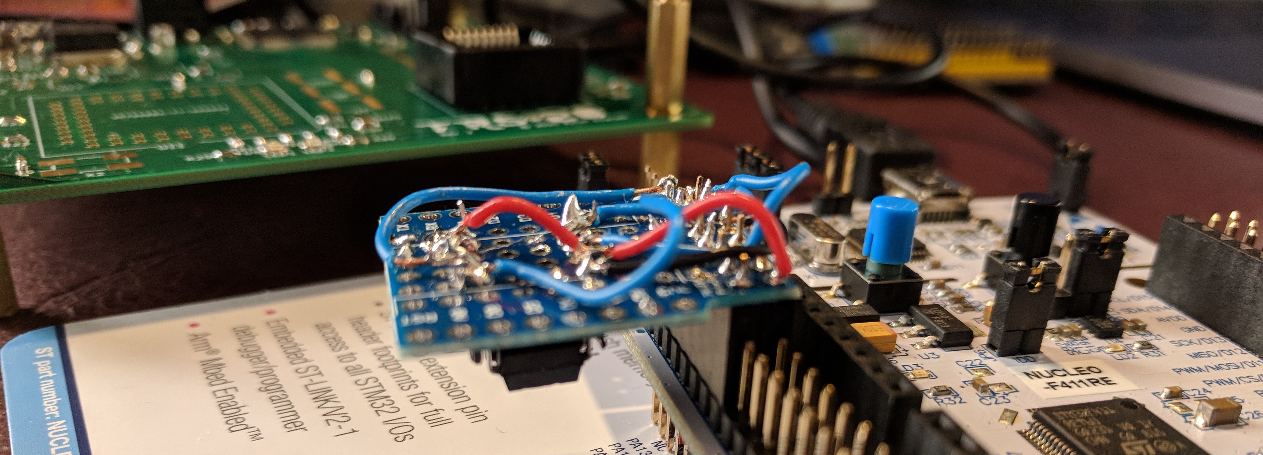
Pin selection for the SPI ROM is a little fiddly, as STM32CubeMX presents me with an image of the IC’s pins, but I care about the board’s layout. The ’F411 has five SPI peripherals, and each peripheral has a few options for pins; after not too much time I’d selected SPI3 using pins PC10, 11, and 12 for SCK, MISO, and MOSI respectively. These pins are all grouped together on a pair of pin headers on one side of the board, close enough to the power pins that a D1 protoshield board with a 2x8 female header can cover GND, 3V3, the three SPI pins, and an arbitrary pin (PD2) for slave select.
The circuit on the protoshield is trivial - a pull-up for /CS and a socket for the ROM - and you can see my handiwork in the image at the top of the post.
I won’t go into detail on the code work involved. I wrote a simple interface for the Flash ROM, and implemented a YModem receiver so I could upload over the ST-LINK’s USB serial port.
I burned on a simple image that just sets one LED to be always off, and binds the other to the 100MHz oscillator’s input via a 26-bit counter. This is around a 1.5Hz blink - if it works.
module poc(CLK1, LED1, LED2);

    input CLK1;
    output              LED1, LED2;

    assign LED1 = 0;

    reg [25:0]          counter;
    reg                 toggle;

    always @(posedge CLK1)
        counter <= counter + 1'b1;

    assign LED2 = counter[25];

endmodule
While I was at it, I figured I may as well make two images like this, one with assign LED1 = 0; and the other with assign LED1 = 1;. Project IceStorm supports multi-image bitstreams, so I can exercise my boot selector jumpers as well.
After straightening the ROM’s pins back out (use a removal tool: flat tweezers are excellent, fingers are not) and plugging it into the main board, well:
I stared at a blinking light for a somewhat absurd amount of time. The FPGA works. The oscillator works. The ROM works. The power works. Job more or less done!
The parallel ROM
I thought about how I might want to do this. A neat job would be female headers on a board for the Nucleo to plug into, programming the ROM IC in a PLCC socket beside it. I could add a DIP8 socket and have a programmer for both ROMs in short order. But this is a lot of jumper wires to mess about with, and frankly I’m not really keen on it. So - pretty much every jumper lead I have is now in Frankenprogrammer.
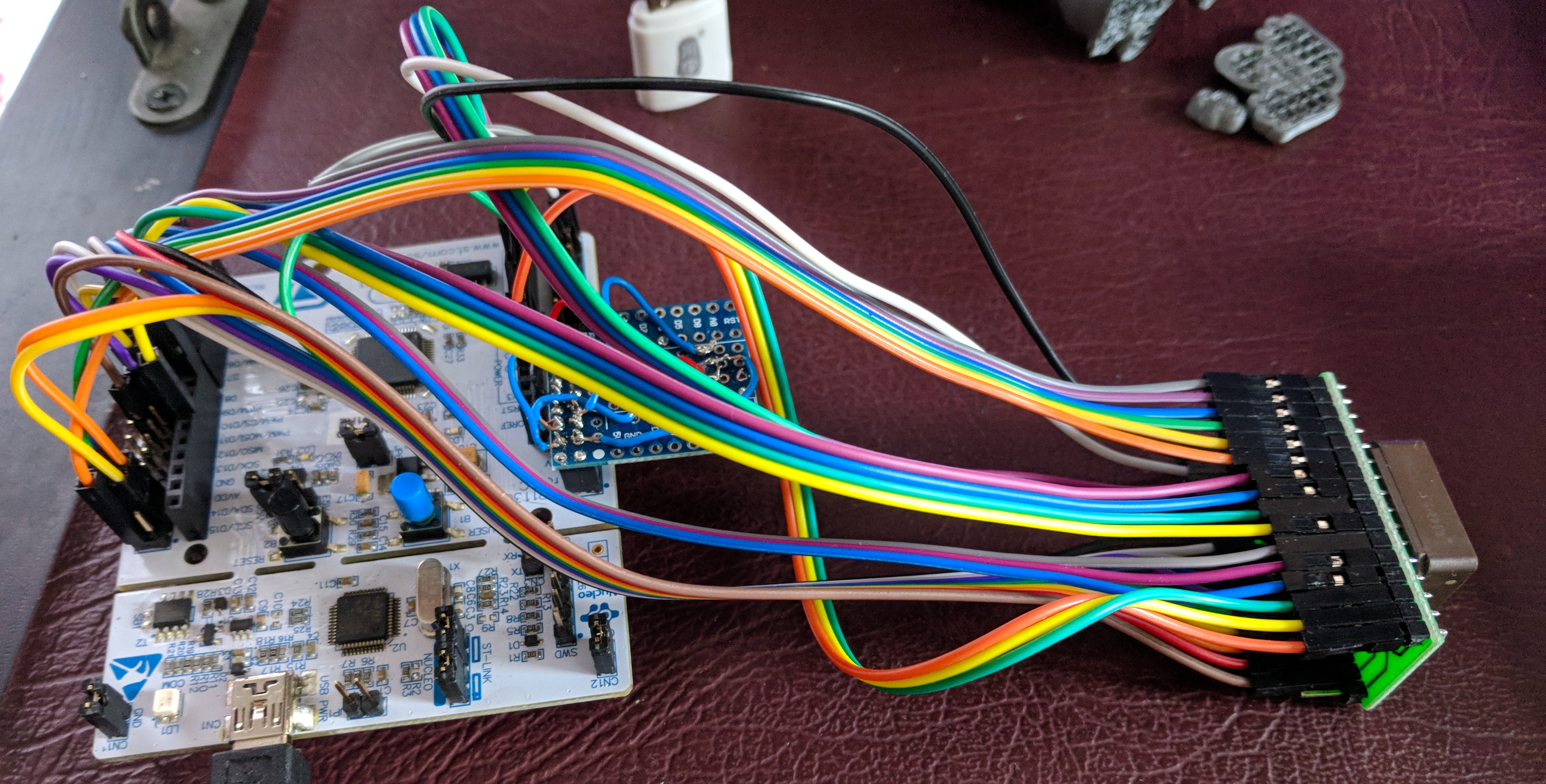
I hope to minimise my programming cycles - I need to work out how I can verify the whole CPU board is good, then work on producing enough of a ROM that I can boot up to something that’ll program other parts of the ROM over USB. PLCC sockets are only good for a few tens of insertions, so I want to be bootstrapped on-board ASAP.
Next up: completing the CPU board assembly.